System Design & Drawings
When completing electrical installation or upgrade projects, delivering accurate system design and drawings, including CAD updates, is crucial for proper documentation, future maintenance, and compliance.
-
Detailed drawings serve as a reference for installation, troubleshooting, and future upgrades. We ensure that the installation meets local codes and standards. Drawings help to provide clear communication between engineers, contractors, and clients regarding the installation specifics.
-
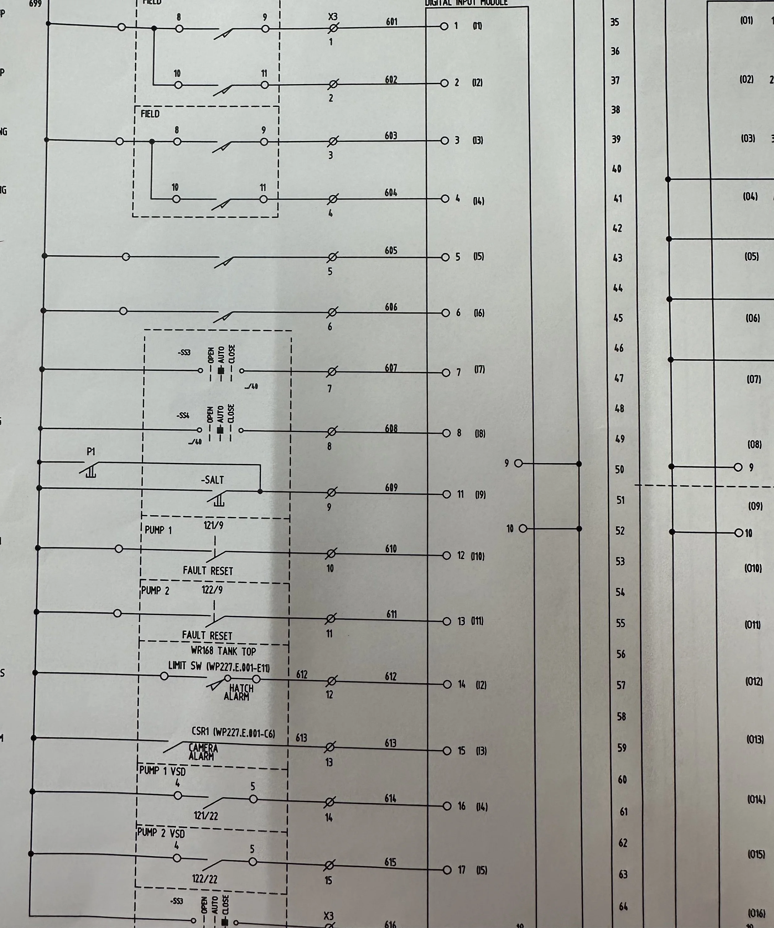
Displays how electrical components are connected and the flow of electricity. An SLD showing the connection between the main switchboard, sub-panels, and generators. Provides detailed information on the wiring connections and configurations. Useful for troubleshooting and identifying circuit paths.
A wiring diagram detailing the connections for an Automatic Transfer Switch (ATS). Show the physical arrangement of electrical equipment within the facility. Include dimensions, clearance requirements, and equipment spacing. A layout drawing of a switchboard room, including the generator placement and ATS.
Lists all cables used in the project, including type, size, length, and routing. Important for budgeting and planning future maintenance. A cable schedule detailing the specifications for power and control cables. Document the calculations used to determine the electrical load requirements.
Essential for justifying the size of the generator and switchboard. A load calculation chart showing critical loads and total demand.
-
We use layers effectively to separate different types of information (e.g., power, lighting, circuits). Utilize standard symbols and annotations for clarity and consistency.
-
We ensure that they are aligned with the project specifications and client requirements. Obtain approval from relevant stakeholders (e.g., project manager, client). Incorporate any changes made during the installation phase into the CAD drawings. Ensure that all changes are accurately reflected in the final documentation. Compile a comprehensive handover package that includes All drawings (SLD, wiring diagrams, layout drawings). Cable schedules and load calculations. Maintenance manuals and warranties for installed equipment. Provide digital copies in PDF and editable CAD formats.
-
We offer training sessions for facility staff on how to interpret and use the drawings. Establish a process for updating the documentation in case of future modifications or upgrades.
Why choose us?
The provision of detailed system designs and CAD drawings at the conclusion of electrical installation or upgrade projects is essential. It not only ensures compliance and facilitates future maintenance but also enhances communication among all parties involved.
By following the structured approach outlined above, you can deliver high-quality documentation that supports the long-term success of the electrical system.